
For the Seattle Central Library project, one of the most challenging aspects of the construction was the fabrication and erection of the "seismic steel" that formed the structural support of the facade and also provided most of the lateral stability of the building.
Computer modeling of the building geometry provided dimensional control during both fabrication and installation phases. See related post for a description of how BIM was used to ensure dimensional accuracy during the detailing and fabrication. This post focuses on how the digital model was used to tightly control the erection of the steel to meet the exacting tolerances required for the construction.
Steel erection was performed by The Erection Company of Seattle, and the survey control was performed by Ming Survey, a subsidiary of Hoffman Construction, the General Contractor / Construction Manager.
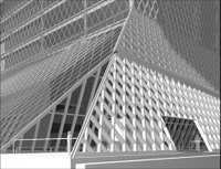
The panels are comprised of 12" deep wide flange steel beams welded together into a diamond lattice pattern. Each diamond is 4'-0" wide at the midpoint and built on a 60 degree angle. The panels were shop fabricated in approximately 12 foot widths (to allow truck shipment) and in the lengths required for the span. There were three different conditions, under slung (shown here), overhead, and corner conditions. The under slung panels were among the most difficult to erect because of the challenges associated with hoisting them into position within the building's primary structure.
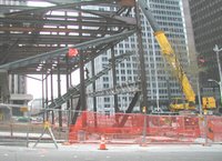
Here some of the overhead panels are being erected. These are some of the longest panels on the project.
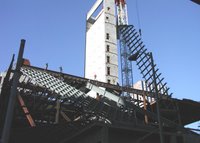
This image depicts an infill panel being placed on a building corner condition. Note the temporary erection aides to assist in securing the assembly. Once the panels are final set and welded together these pieces are removed.

All the seismic steel needed to be set to within +/- 1/2" tolerance because it is geometrically associated with the curtain wall mullions. Since the seismic steel provides the lateral support for the building (even during construction) it was necessary to very quickly determine whether the steel was placed accurately. Once this was confirmed the panels could be welded together and and only then would they form a 2-way grid that stabilized the structure.
Until the structure was properly stabilized the crews were limited regarding how tall the building could be built and remain stable. Thus the surveying of the seismic steel was on the critical path of the construction and needed to be performed quickly, accurately and safely.

This was accomplished by utilizing a digital laser scanner. This equipment utilizes a pulsing laser that oscillates frequency and shines onto a spinning prism. The prism's rotation is synchronized with the laser pulse to array the projected light across the field of view of the scanner. The point density can be set by the user - the denser the array the more precise the model becomes but of course this affects the file size and the time required for the scan.

This was accomplished by utilizing a digital laser scanner. This equipment utilizes a pulsing laser that oscillates frequency and shines onto a spinning prism. The prism's rotation is synchronized with the laser pulse to array the projected light across the field of view of the scanner. The point density can be set by the user - the denser the array the more precise the model becomes but of course this affects the file size and the time required for the scan.
The laser light reflects off the surface it strikes and a sensor on the instrument records the time it takes for the pulse to return. Dividing this time by the speed of light and by 2 produces a distance to the reflecting surface which, when combined with the vector the pulse was projected on produces an x,y,z coordinate for the point. Because the laser frequency oscillates, the instrument can differentiate between two pulses that return to the sensor at nearly the same instant.
The entire group of points is called a "point cloud" and represents a very accurate although highly pixellated as-built survey of the building.
Special targets are placed throughout the scan area. These are recognized by the scanning software and their locations stored in a special file. The scanner can be set up in multiple locations and as long as at least three common targets are visible in the scans, the software can combine scans together into single data files. This approach reduces or eliminates the "shadow effect" that any single point of view will have, producing a more complete image. The scans also require at least three known x,y,z coordinates to be supported in the file to allow the data to be incorporated into a 3D CAD environment.

While the point clouds are valuable, of much greater value is a surface model created from the points. In addition to position, the instrument also records the reflected light intensity, and points with very similar intensity values can be understood to be common to the same surface. Similarly, points associated with a curved surface, such as a pipe, can be grouped together by the software. The software also has a library of standard shapes. In this example, we were interested in 12" deep wide-flange steel beams which have a known profile, and the software is capable of grouping these sets of points together intelligently and fairly easily in an operation that is similar to an extrusion command in 3D CAD.

While the point clouds are valuable, of much greater value is a surface model created from the points. In addition to position, the instrument also records the reflected light intensity, and points with very similar intensity values can be understood to be common to the same surface. Similarly, points associated with a curved surface, such as a pipe, can be grouped together by the software. The software also has a library of standard shapes. In this example, we were interested in 12" deep wide-flange steel beams which have a known profile, and the software is capable of grouping these sets of points together intelligently and fairly easily in an operation that is similar to an extrusion command in 3D CAD.

The next step is to generate an excerpted model of the steel in it's idealized location. This comes form the 3D CAD model that was produced by the steel detailers.

By overlaying the theoretical 3D CAD data with the as-built laser scan surface model, the two models can be compared to each other to determine where the steel is out of tolerance.

The specified tolerance of the steel is +/- 1/2" so in areas where the steel is outside this allowable range dimensions are added to the model to communicate these conditions.

Because the model is in a 3D environment, it can be rotated into a convenient orientation to communicate the information to the field.

By utilizing this approach, the relevant data was able to be generated quickly, accurately and safely, and communicated in a way that was easily understood by the steel crews.
Typically, the steel panels were placed and temporarily braced during a work shift and scanned at the end of the day. During the evening the modelling work was performed and data was analyzed. The next day the iron workers had the information they needed to make the necessary adjustments. The steel was then scanned again for final fit and assuming it was correct the welding could commence beginning on day three of the operation. This represents a very significant schedule and quality improvement compared with a conventional approach and had the added benefits of saving survey labor and eliminating the need to climb the steel to take the measurements.

No comments:
Post a Comment