Much has been written about the collaborative potential of Building Information Model (BIM) tools. On the Seattle Central Library project, Hoffman Construction (General Contractor / Construction Manager) was working with a World-Class group of design, engineering and fabrication resources and used BIM to facillitate collaboration between the key parties. While this was extremely successful it proved to be a challenge to implement. Photo by Lara Swimmer Photography.
The project was publicly funded using the Washington State CM/GC procurement approach which allows a contractor to participate in a pre-construction role prior to the bids being awarded. This was very beneficial to the process of advancing the project from design to construction but it did not, however, allow for the subcontracts to be let prior to the completion of the design packages. As a result, implementing a collaborative approach to using BIM with the key subcontractors required this to be done by contractual mandate in the bid package documentation.

The architectural design was produced by Dutch architect Rem Koolhaas and the Office for Metropolitan Architecture in a joint venture with Seattle-based LMN Architects (OMA/LMN).

Seattle-based Magnusson Klemencic Associates (MKA) provided the Structural and Civil engineering for the project. ARUP also participated in the structural engineering during the schematic design phase of the project. This image by MKA depicts the primary load path of the structure (vertical load only).

Lateral loads such as wind and seismic are resisted by a grid of steel beams in a diamond pattern. This system, called the "seismic steel" during the project, also does double-duty by providing direct support of the building curtain wall system. By directly associating the steel with the curtain wall, the window system spans are greatly reduced which minimizes the cost of the cladding system. Image by MKA.

Because the steel and the curtain wall systems were so directly associated, it was essential that an approach was implemented that ensured both systems used identical geometry. The complexity of the geometry meant that traditional approaches to quality assurance (error trapping) would not be successful since even subtle differences between steel and curtain wall would produce a fit-up failure. Since all facade components were pre-fabricated off-site, replacement of components would be prohibitively expensive and time-consuming. Photo by Hoffman.

This photo by Hoffman shows the seismic steel (painted blue) with the aluminum mullions attached (right side of image) and the connecting brackets installed (center and left of image). The steel was erected by The Erection Company of Seattle and fabricated by Canron in Vancouver, BC and Portland, OR.
Curtain wall design-build subcontractor was Seele GmbH & Co. based in Gersthofen, Germany.

This image of the Seele brackets shows the configuration of slotted holes which allow for adjustment in two directions (x,y). Shims (not pictured) placed between the brackets and the seismic steel provide similar adjustment in the "z" direction.

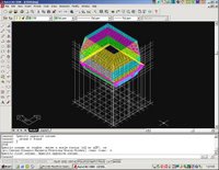
This is the wireframe model of the glazing system by Seele. Elements of the model were produced in a series (not in "parallel"). Hoffman established the site coordinate parameters that all parties utilized. Seele produced the wireframe model for the glazing system and then developed their object based window components off these wires.

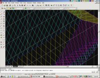
Detail of Seele wireframe model. Lines represent centerline of mullions at outside face of glass.

2D Fabrication drawing by Seele indicating one of the many different fold line conditions. Details such as these were generated to tightly coordinate the interface between the curtainwall system and the steel supports.

Once the geometrical realities of the curtain wall components were modelled, the file could be transmitted to BDS Steel Detailiners, in their Phoenix, AZ office. By offsetting the Seele wireframe model by the various thicknesses of the curtain wall faces, a corresponding wireframe was created representing centerlines of the seismic steel at the top (outside) surface of the wide flanges.

With applications like Xsteel, SDS (and others), steel detailers spend most of their production time generating detail in the model, including welds, bolts, erection aides, etc. The fabrication and placement drawings that are necessary for the construction teams are essentially reports that come from this data. A key benefit to this approach is that the connections are modeled once, so all members associated with a connection are sure to fit as long as they are properly fabricated.

In this image, the Xsteel model is partially complete. The member shapes have been extruded along the wireframe geometry but not yet trimmed at the ends. This model is then trasmitted to the Mechanical contractor, McKinstry Co. of Seattle, WA. as well as others.

Once these mechanical systems are modeled the data can be transmitted back to the steel detailers and used to inform the locations of the various penetrations through the steel that were required.

By carefully coordinating the roles of the key fabricators a tremendous amount of value can be generated, particularily on projects that have significant complexity. Critical to the success is to utilize the existing capabilities of the resources involved and to leverage the efforts that are already being expended.

The architectural design was produced by Dutch architect Rem Koolhaas and the Office for Metropolitan Architecture in a joint venture with Seattle-based LMN Architects (OMA/LMN).
The building design involves a series of platforms that are organized to meet the specific program requirements of the Library. Model by OMA/LMN.

Seattle-based Magnusson Klemencic Associates (MKA) provided the Structural and Civil engineering for the project. ARUP also participated in the structural engineering during the schematic design phase of the project. This image by MKA depicts the primary load path of the structure (vertical load only).

Lateral loads such as wind and seismic are resisted by a grid of steel beams in a diamond pattern. This system, called the "seismic steel" during the project, also does double-duty by providing direct support of the building curtain wall system. By directly associating the steel with the curtain wall, the window system spans are greatly reduced which minimizes the cost of the cladding system. Image by MKA.

Because the steel and the curtain wall systems were so directly associated, it was essential that an approach was implemented that ensured both systems used identical geometry. The complexity of the geometry meant that traditional approaches to quality assurance (error trapping) would not be successful since even subtle differences between steel and curtain wall would produce a fit-up failure. Since all facade components were pre-fabricated off-site, replacement of components would be prohibitively expensive and time-consuming. Photo by Hoffman.

This photo by Hoffman shows the seismic steel (painted blue) with the aluminum mullions attached (right side of image) and the connecting brackets installed (center and left of image). The steel was erected by The Erection Company of Seattle and fabricated by Canron in Vancouver, BC and Portland, OR.
Curtain wall design-build subcontractor was Seele GmbH & Co. based in Gersthofen, Germany.

This image of the Seele brackets shows the configuration of slotted holes which allow for adjustment in two directions (x,y). Shims (not pictured) placed between the brackets and the seismic steel provide similar adjustment in the "z" direction.
The slot lengths allow for up to +/- 1/2" of tolerance in the location of the seismic steel. This is significantly tighter than industry standard but if more lenient tolerances were accepted the brackets would need to be much larger and the mullions could become visually disassociated from the seismic steel.

This is the wireframe model of the glazing system by Seele. Elements of the model were produced in a series (not in "parallel"). Hoffman established the site coordinate parameters that all parties utilized. Seele produced the wireframe model for the glazing system and then developed their object based window components off these wires.

Detail of Seele wireframe model. Lines represent centerline of mullions at outside face of glass.

2D Fabrication drawing by Seele indicating one of the many different fold line conditions. Details such as these were generated to tightly coordinate the interface between the curtainwall system and the steel supports.

Once the geometrical realities of the curtain wall components were modelled, the file could be transmitted to BDS Steel Detailiners, in their Phoenix, AZ office. By offsetting the Seele wireframe model by the various thicknesses of the curtain wall faces, a corresponding wireframe was created representing centerlines of the seismic steel at the top (outside) surface of the wide flanges.
BDS then incorporated this geometry into their Xsteel model that also contained the primary structure.

With applications like Xsteel, SDS (and others), steel detailers spend most of their production time generating detail in the model, including welds, bolts, erection aides, etc. The fabrication and placement drawings that are necessary for the construction teams are essentially reports that come from this data. A key benefit to this approach is that the connections are modeled once, so all members associated with a connection are sure to fit as long as they are properly fabricated.

In this image, the Xsteel model is partially complete. The member shapes have been extruded along the wireframe geometry but not yet trimmed at the ends. This model is then trasmitted to the Mechanical contractor, McKinstry Co. of Seattle, WA. as well as others.
The locations of the structural steel elements is important in coordinating the routing of the various mechanical elements such as ductwork, piping and conduit.

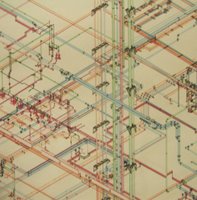
Here is an image of the HVAC ductwork for the buiding. Because components such as ductwork are generally made using sophisticated CAD-CAM equipment, ductwork components are modelled as intellegent objects and these objects can be output directly to the fabrication equipment for part stamping, folding and some assembly.

Here is an image of the HVAC ductwork for the buiding. Because components such as ductwork are generally made using sophisticated CAD-CAM equipment, ductwork components are modelled as intellegent objects and these objects can be output directly to the fabrication equipment for part stamping, folding and some assembly.

Once these mechanical systems are modeled the data can be transmitted back to the steel detailers and used to inform the locations of the various penetrations through the steel that were required.

By carefully coordinating the roles of the key fabricators a tremendous amount of value can be generated, particularily on projects that have significant complexity. Critical to the success is to utilize the existing capabilities of the resources involved and to leverage the efforts that are already being expended.
Trying to implement this approach with participants who do not have this level of expertise, or requiring a party to perform tasks they do not ordinarily perform could result in a lack of successful collaboration.


No comments:
Post a Comment