Saturday, November 18, 2006

Using Digital Laser Scanning on the Seattle Central Library


For the Seattle Central Library project, one of the most challenging aspects of the construction was the fabrication and erection of the "seismic steel" that formed the structural support of the facade and also provided most of the lateral stability of the building.


Computer modeling of the building geometry provided dimensional control during both fabrication and installation phases. See related post for a description of how BIM was used to ensure dimensional accuracy during the detailing and fabrication. This post focuses on how the digital model was used to tightly control the erection of the steel to meet the exacting tolerances required for the construction.
Steel erection was performed by The Erection Company of Seattle, and the survey control was performed by Ming Survey, a subsidiary of Hoffman Construction, the General Contractor / Construction Manager.


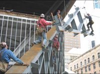
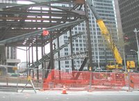
The panels are comprised of 12" deep wide flange steel beams welded together into a diamond lattice pattern. Each diamond is 4'-0" wide at the midpoint and built on a 60 degree angle. The panels were shop fabricated in approximately 12 foot widths (to allow truck shipment) and in the lengths required for the span. There were three different conditions, under slung (shown here), overhead, and corner conditions. The under slung panels were among the most difficult to erect because of the challenges associated with hoisting them into position within the building's primary structure.


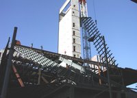
Here some of the overhead panels are being erected. These are some of the longest panels on the project.


This image depicts an infill panel being placed on a building corner condition. Note the temporary erection aides to assist in securing the assembly. Once the panels are final set and welded together these pieces are removed.


All the seismic steel needed to be set to within +/- 1/2" tolerance because it is geometrically associated with the curtain wall mullions. Since the seismic steel provides the lateral support for the building (even during construction) it was necessary to very quickly determine whether the steel was placed accurately. Once this was confirmed the panels could be welded together and and only then would they form a 2-way grid that stabilized the structure.
Until the structure was properly stabilized the crews were limited regarding how tall the building could be built and remain stable. Thus the surveying of the seismic steel was on the critical path of the construction and needed to be performed quickly, accurately and safely.


This was accomplished by utilizing a digital laser scanner. This equipment utilizes a pulsing laser that oscillates frequency and shines onto a spinning prism. The prism's rotation is synchronized with the laser pulse to array the projected light across the field of view of the scanner. The point density can be set by the user - the denser the array the more precise the model becomes but of course this affects the file size and the time required for the scan.
The laser light reflects off the surface it strikes and a sensor on the instrument records the time it takes for the pulse to return. Dividing this time by the speed of light and by 2 produces a distance to the reflecting surface which, when combined with the vector the pulse was projected on produces an x,y,z coordinate for the point. Because the laser frequency oscillates, the instrument can differentiate between two pulses that return to the sensor at nearly the same instant.
The entire group of points is called a "point cloud" and represents a very accurate although highly pixellated as-built survey of the building.
Special targets are placed throughout the scan area. These are recognized by the scanning software and their locations stored in a special file. The scanner can be set up in multiple locations and as long as at least three common targets are visible in the scans, the software can combine scans together into single data files. This approach reduces or eliminates the "shadow effect" that any single point of view will have, producing a more complete image. The scans also require at least three known x,y,z coordinates to be supported in the file to allow the data to be incorporated into a 3D CAD environment.


While the point clouds are valuable, of much greater value is a surface model created from the points. In addition to position, the instrument also records the reflected light intensity, and points with very similar intensity values can be understood to be common to the same surface. Similarly, points associated with a curved surface, such as a pipe, can be grouped together by the software. The software also has a library of standard shapes. In this example, we were interested in 12" deep wide-flange steel beams which have a known profile, and the software is capable of grouping these sets of points together intelligently and fairly easily in an operation that is similar to an extrusion command in 3D CAD.


The next step is to generate an excerpted model of the steel in it's idealized location. This comes form the 3D CAD model that was produced by the steel detailers.


By overlaying the theoretical 3D CAD data with the as-built laser scan surface model, the two models can be compared to each other to determine where the steel is out of tolerance.


The specified tolerance of the steel is +/- 1/2" so in areas where the steel is outside this allowable range dimensions are added to the model to communicate these conditions.


Because the model is in a 3D environment, it can be rotated into a convenient orientation to communicate the information to the field.


By utilizing this approach, the relevant data was able to be generated quickly, accurately and safely, and communicated in a way that was easily understood by the steel crews.
Typically, the steel panels were placed and temporarily braced during a work shift and scanned at the end of the day. During the evening the modelling work was performed and data was analyzed. The next day the iron workers had the information they needed to make the necessary adjustments. The steel was then scanned again for final fit and assuming it was correct the welding could commence beginning on day three of the operation. This represents a very significant schedule and quality improvement compared with a conventional approach and had the added benefits of saving survey labor and eliminating the need to climb the steel to take the measurements.
Implementing a "Federated BIM" on the Seattle Central Library


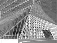
Much has been written about the collaborative potential of Building Information Model (BIM) tools. On the Seattle Central Library project, Hoffman Construction (General Contractor / Construction Manager) was working with a World-Class group of design, engineering and fabrication resources and used BIM to facillitate collaboration between the key parties. While this was extremely successful it proved to be a challenge to implement. Photo by Lara Swimmer Photography.

The project was publicly funded using the Washington State CM/GC procurement approach which allows a contractor to participate in a pre-construction role prior to the bids being awarded. This was very beneficial to the process of advancing the project from design to construction but it did not, however, allow for the subcontracts to be let prior to the completion of the design packages. As a result, implementing a collaborative approach to using BIM with the key subcontractors required this to be done by contractual mandate in the bid package documentation.


The architectural design was produced by Dutch architect Rem Koolhaas and the Office for Metropolitan Architecture in a joint venture with Seattle-based LMN Architects (OMA/LMN).
The building design involves a series of platforms that are organized to meet the specific program requirements of the Library. Model by OMA/LMN.


Seattle-based Magnusson Klemencic Associates (MKA) provided the Structural and Civil engineering for the project. ARUP also participated in the structural engineering during the schematic design phase of the project. This image by MKA depicts the primary load path of the structure (vertical load only).


Lateral loads such as wind and seismic are resisted by a grid of steel beams in a diamond pattern. This system, called the "seismic steel" during the project, also does double-duty by providing direct support of the building curtain wall system. By directly associating the steel with the curtain wall, the window system spans are greatly reduced which minimizes the cost of the cladding system. Image by MKA.


Because the steel and the curtain wall systems were so directly associated, it was essential that an approach was implemented that ensured both systems used identical geometry. The complexity of the geometry meant that traditional approaches to quality assurance (error trapping) would not be successful since even subtle differences between steel and curtain wall would produce a fit-up failure. Since all facade components were pre-fabricated off-site, replacement of components would be prohibitively expensive and time-consuming. Photo by Hoffman.


This photo by Hoffman shows the seismic steel (painted blue) with the aluminum mullions attached (right side of image) and the connecting brackets installed (center and left of image). The steel was erected by The Erection Company of Seattle and fabricated by Canron in Vancouver, BC and Portland, OR.

Curtain wall design-build subcontractor was Seele GmbH & Co. based in Gersthofen, Germany.


This image of the Seele brackets shows the configuration of slotted holes which allow for adjustment in two directions (x,y). Shims (not pictured) placed between the brackets and the seismic steel provide similar adjustment in the "z" direction.
The slot lengths allow for up to +/- 1/2" of tolerance in the location of the seismic steel. This is significantly tighter than industry standard but if more lenient tolerances were accepted the brackets would need to be much larger and the mullions could become visually disassociated from the seismic steel.


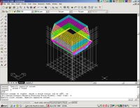
This is the wireframe model of the glazing system by Seele. Elements of the model were produced in a series (not in "parallel"). Hoffman established the site coordinate parameters that all parties utilized. Seele produced the wireframe model for the glazing system and then developed their object based window components off these wires.


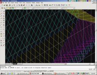
Detail of Seele wireframe model. Lines represent centerline of mullions at outside face of glass.


2D Fabrication drawing by Seele indicating one of the many different fold line conditions. Details such as these were generated to tightly coordinate the interface between the curtainwall system and the steel supports.


Once the geometrical realities of the curtain wall components were modelled, the file could be transmitted to BDS Steel Detailiners, in their Phoenix, AZ office. By offsetting the Seele wireframe model by the various thicknesses of the curtain wall faces, a corresponding wireframe was created representing centerlines of the seismic steel at the top (outside) surface of the wide flanges.
BDS then incorporated this geometry into their Xsteel model that also contained the primary structure.


With applications like Xsteel, SDS (and others), steel detailers spend most of their production time generating detail in the model, including welds, bolts, erection aides, etc. The fabrication and placement drawings that are necessary for the construction teams are essentially reports that come from this data. A key benefit to this approach is that the connections are modeled once, so all members associated with a connection are sure to fit as long as they are properly fabricated.


In this image, the Xsteel model is partially complete. The member shapes have been extruded along the wireframe geometry but not yet trimmed at the ends. This model is then trasmitted to the Mechanical contractor, McKinstry Co. of Seattle, WA. as well as others.
The locations of the structural steel elements is important in coordinating the routing of the various mechanical elements such as ductwork, piping and conduit.


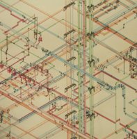
Here is an image of the HVAC ductwork for the buiding. Because components such as ductwork are generally made using sophisticated CAD-CAM equipment, ductwork components are modelled as intellegent objects and these objects can be output directly to the fabrication equipment for part stamping, folding and some assembly.


Similarly, the mechanical piping routing is added to the model environment.


Once these mechanical systems are modeled the data can be transmitted back to the steel detailers and used to inform the locations of the various penetrations through the steel that were required.


By carefully coordinating the roles of the key fabricators a tremendous amount of value can be generated, particularily on projects that have significant complexity. Critical to the success is to utilize the existing capabilities of the resources involved and to leverage the efforts that are already being expended.
Trying to implement this approach with participants who do not have this level of expertise, or requiring a party to perform tasks they do not ordinarily perform could result in a lack of successful collaboration.

Tuesday, November 14, 2006

CATIA and the Experience Music Project

Hoffman Construction was selected as the Construction Manager/General Contractor for the Experience Music Project in Seattle, WA. This involved utilizing the CATIA model information provided by the team from Gehry Partners, the Architect. At the time, nobody at Hoffman had any background in working in a 3D CAD envoronment, and certainly no knowledge of using CATIA. Over the course of the construction, not only was the use of BIM something that was embraced and used extensively, BIM has become an important initiative for utilization on a wide variety of projects in the portfolio of projects built since EMP.

At that time, Gehry Partners was using CATIA V4, and their output was primarily in the form of wireframe assemblies (not many surfaces and no objects). It was a huge challenge to convert this data into a form that was usable in construction.


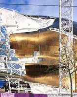
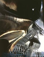
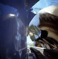
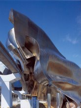
One of the most complex areas of the building is the gold clad sculptural element that cantilevers over the existing Monorail tracks. This part of the building was called the "Madonna Wall" during the design and construction.

The support system behind this cladding is very extensive and was very difficult to construct, partly due to the fact that the monorail needed to remain active throughout operating hours, requiring all work to be done between 11:00pm and 6:00am. This meant that accurate communication and thourough work planning were high priorities.


An early CATIA study model showing the various steel elements that comprise the cantilevered support system for the cladding.

The dark "ribs" are the primary support members, and the colored members are a space frame system that reaches out to support the cladding panels.


The steel detailers, Angle Detailing, imported the CATIA wireframe model into AutoCAD because they were more familiar with generating drawings in this software.


The wireframe was then extruded to reflect the true sizes of the members. This is an important step that allows for clash detection and other error trapping efforts.


Elements such as splice plates, clips and braces are added to the model. Splices are located to facilitate shipment of assemblies and erection of the steel withing the tight geometry constraints.


Assembly drawings are produced that include jig frames for fabricating the parts and welding them together.


Many detail drawings were required to document the specific relationship of the parts.


Detail of shop welded connection.


Partial assembly, ready for galvanizing. Bolted flange connections are loose-fit to preserve alignment between sections.

Fabrication was by Columbia Wire and Iron, Portland, OR.


Frames installed onto structural ribs. Steel erection was by CARR Construction.


This image gives an idea of the overhang geometry of the primary structure.


Cladding panels being installed over the structural supports.


Cladding panels nearly complete. Cladding was fabricated by A. Zahner Company.


Case Western Reserve Paper on BIM Innovation

This is a paper written on innovation in AEC, specifically dealing with contractors who work on Frank Gehry projects and what happens to them after they move onto the next one.

It starts out rather theoretical, but beginning on page 200 it focuses on a case study comparing the evolution of CATIA-based BIM innovation on the Experience Music Project in Seattle, and the BIM-enabled construction of the Koolhaas Seattle Central Library project.